GPRP Diesel

This package is designed for direct injection, common rail, turbo diesel engines, but can also be used for naturally aspirated diesel applications. Many features of MoTeC's petrol GPR packages have been reproduced in this package, providing a familiar feel for current GPR users.

Many auxiliary features commonly found on racing cars are included, such as launch control, traction control, driver switches (e.g., pit switch, launch enable, boost compensation), gearbox control, intercooler sprays, transmission pump, differential pump, and coolant pump. Also accommodated are many systems found on modified road vehicles, such as air conditioning.

The package fully integrates with other MoTeC products and provides predefined CAN messages for all current display loggers, recorders, E888, VCS, GPS, ADR, BR2, PDM and SLM. A vector database file (.dbc) is also available upon request.

Features

The following GPR Diesel features are specifically designed to operate diesel engines:

  • Operates 1- to 8-cylinder direct injection diesel engines with inductive or piezoelectric injectors and synchronous direct injection fuel pumps. See section Engine compatibility to obtain the known applicable mechanisms.
  • Turbocharger boost pressure control from a PWM solenoid or servo motor for use with a Variable Nozzle Turbo (VNT), Wastegate, Bypass, etc. Boost control is fully configurable via a PID control system giving the user full control over system response and stability. Boost Aim can vary based on fuel mass, engine speed and ambient pressure.

    To ensure safe operation, various boost limits can also be set. These limits can be based on coolant temperature, engine load, exhaust temperature, intake air temperature, run time, gear, vehicle speed, and turbocharger speed.

  • Control of a throttle valve is also supported. This throttle valve can be used to assist in engine shutdown or reduce power during Engine Run-Over Operation.
  • Exhaust gas recirculation control via a servo motor, solenoid or stepper motor actuator. The amount of EGR applied can vary with engine speed and fuel mass. Compensations for air temperature, coolant temperature and ambient pressure can also be applied.

    A start-up EGR compensation can be used to prevent soot formation when the vehicle takes off. Separate EGR targets can be used for Overrun and Gear Shifts. The Throttle Servo or a Flap Actuator (EGR Cooler) can also be controlled during EGR requests.

  • The glow plug control system includes independent strategies for controlling the glow plugs before starting, during starting and after starting. Each stage has adjustable compensations for coolant temperature and battery voltage.
  • Ignition outputs are available for each cylinder to check fuel injection timing.
  • Advanced LTC Enable functionality ensures safe operation of Lambda sensors.

Adapter kits for common diesel vehicles will be available soon. These adapter kits connect the vehicle's original engine harness directly to the M1 without the need to modify the existing OE wiring.

The following sensors are required to operate a diesel engine with this GPR Diesel package:

  • Coolant temperature sensor
  • Direct Fuel Pressure Sensor (Common Rail)
  • Mass air flow sensor or intake manifold pressure sensor and intake air temperature sensor (all 3 preferred)
  • Accelerator pedal sensor
  • Engine speed reference sensor
  • Engine timing sensor (camshaft position)

For optimal performance, the following sensors are recommended for use with the GPR Diesel package:

  • Exhaust temperature sensor
  • Boost pressure sensor
  • Fuel temperature sensor
  • Ambient pressure sensor

This package is available for use with MoTeC direct injection ECUs: M141 and M142. A package variant for M130 and M150 ECUs is also available and is used in conjunction with an injector drive box fitted to some vehicles (e.g. Toyota Hilux).

The main difference between MoTeC's M141 and M142 ECUs is the maximum available boost voltage and peak/hold currents for direct injector operation. Consequently, the injector power requirements of any engine must be considered when choosing an M1 ECU.

ECUMaximum reinforcement stressMaximum peak currentMaximum holding current
M141188V20ONE10ONE
M14280V20ONE15ONE

See section Engine compatibility of this datasheet to determine the correct ECU for the application. Below is a sample pinout for the M142.

GPRP Features

The following features of the MoTeC GPR Package are retained in the GPR Diesel Package:

  • Configurable engine timing mode for many common engine types. See section Engine synchronization modes for current details.
  • Configurable top dead center for each cylinder allows for odd-firing engines.
  • Configurable camshaft control from 1 to 4 cams, plus 1 switched camshaft.
  • Physical settings for engine displacement, fuel properties and injector characteristics allow for simplified engine start-up prior to tuning.
  • Sensor calibrations are available for many common automotive sensors. Sensor calibrations can also be set manually.
  • Support for analog and digital sensors (frequency or duty cycle).
  • Support for single-wire digital sensors (SENT).
  • Diagnostics on all sensors to check for high and low shorts. When diagnostics detect a fault, the package either disables all functions that use the faulty sensor or uses the sensor's default estimates. The air box mass flow sensor has extra plausibility diagnostics to check for shift and gain faults.
  • Support for MoTeC devices: ADR, E8XX, PDM, SLM, Video Systems
  • Supports CAN messages for BOSCH ABS M4 unit.
  • Test settings for most outputs, including injection and ignition outputs, to make setup easier.
  • Configurable turbocharger bypass (blow-off) control.
  • Supports two cooling fan outputs (PWM controlled).
  • Configurable closed loop alternator control system for PWM field winding control.
  • Support for air conditioning with switched output control and optional refrigerant pressure sensor.
  • Cooling pump output with PWM control.
  • Coolant pump after-run functionality, optionally with additional pump output.
  • Engine speed limitation by fuel cutoff.
  • Fuel pump switched output.
  • Fuel Flow Supply Sensor and Fuel Return Flow Sensor.
  • Gearbox position detection via optional dual sensor or engine speed/wheel speed estimation.
  • Gearbox shift request via upshift switch/downshift switch or shift lever force sensor.
  • GPS acquisition and recording via CAN or RS232.
  • Support for GLONASS messages on GPS devices.
  • Intercooler temperature and spray control.
  • Differential temperature control with dedicated temperature sensor and switched pump output.
  • Calculation of the engine load temperature allows correction of the intake air temperature (compensation for the heat absorption effect, etc.).
  • Distance, time and lap number via BR2, GPS or switched input, with split and sector options.
  • Configurable launch control with tables for engine speed, throttle limit, thrust aiming and fuel volume compensation.
  • Race timing system with tables for fuel mass, fuel time, acceleration limit and acceleration limit.
  • Engine load average channel with tables for engine speed limit and boost limit.
  • Intake Manifold Flap Support (actuator with position).
  • Intake manifold support (actuator with position feedback).
  • Assisted engine start control with dedicated fuel mass and idle compensations during cranking and subsequent starting.
  • Total engine running time for engine hour logging.
  • Configurable security for multiple users with different access options.
  • Setting the brake state using a switch or pressure sensor.
  • Setting the clutch state using a switch, a position sensor or a pressure sensor.
  • Transmission brake control ('bump') functionality for perfect positioning of cars, with 'slide' feature.
  • Calculation of clutch slip ratio.
  • ECU internal G-force (acceleration) – longitudinal, lateral, vertical.
  • The ECU CAN receive from a defined CAN ID for receiving data from MoTeC devices.
  • Support of up to three separate CAN buses.
  • Most common ECU channels transmitted over CAN using standard MoTeC CAN models.
  • 8 configurable toggle switches and 8 rotary switches (wired or CAN input) each with 10 positions. They can be simultaneously mapped to Launch Control, Pit Stop, Traction, Race Time Reset, Engine Max Speed Limit, Accelerator Pedal Travel, Boost Limit, Traction Aim and Traction Control Range, Transmission Brake Bump, Wheel Circumference and Wheel Max Speed Limit Switch.
  • Pulsed tachometer output with configurable output pin and scale.
  • Drive by Wire dual bank throttle servo control.
  • Configurable throttle sensor input, with 2-channel analog or single-wire digital (SENT) protocol.
  • Accelerator pedal sensor with translation table. Hybrid OE pedals (e.g. Ford) are supported – one analog and one digital channel.
  • Use of an accelerator pedal sensor or a throttle position sensor in the case of a cable throttle.
  • Differential pump output with user-defined differential temperature control.
  • Transmission cooler pump outlet with user definable transmission temperature control.
  • Traction control with tables for Aim Main, Aim Compensation and Control Range.
  • Measuring vehicle speed using wheel speed sensors, estimation or GPS.
  • Vehicle speed limit control system, which can also be used for well speed limitation.
  • Configurable warning system with light output and CAN.
  • 5 auxiliary output functions for PWM control of actuators added. Output duty cycle control can be varied based on:
    • Engine speed and engine load (Output 1)
    • Engine speed and accelerator pedal (Output 2)
    • Engine Speed and Fuel Mass (Output 3 & 4)
    • Motor speed and auxiliary input (output 5)
  • Optional channels for additional sensors via input pin and/or CAN message, including:
    • Airbox Mass Flow, Mass Flow Reference, Pressure and Temperature
    • Ambient pressure and temperature
    • Boost pressure
    • Front and rear brake pressure
    • Brake switch
    • Brake vacuum pressure
    • Clutch pressure and position
    • Clutch switch
    • Coolant pressure and temperature
    • Differential temperature
    • Engine oil pressure and temperature
    • Engine crankcase pressure
    • Exhaust Pressure Bank 1 and Bank 2
    • Exhaust Temperature (EGT) via TCA thermocouple amplifier, generic CAN or E888 for a single manifold, bank 1 and 2 manifolds and cylinders 1 through 8.
    • Exhaust lambda via LTC, LTCN or PLM to a single manifold, bank 1 and 2 manifolds and cylinders 1 through 8.
    • Fuel pressure and temperature
    • Fuel tank level
    • Gear position
    • Gear lever force
    • Gear neutral switch
    • Gear change request
    • G-force (acceleration) – Longitudinal, Lateral, Vertical
    • Inlet air temperature
    • Intake manifold pressure and temperature
    • Intake manifold flap position x 2, intake manifold runner position
    • Intercooler temperature
    • Steering angle and pressure
    • Transmission pressure and temperature
    • Turbocharger speed
    • Turbocharger inlet/outlet temperature
    • Turbocharger wastegate position
    • Front/rear left/right wheel speed sensors, directly wired or CAN input.

Engine Compatibility

Multipulse injection system

Fuel is supplied by up to four pulses: two pilot, one main, and one post-pulse. Fuel mass is calculated as described in the following section, where the total fuel mass can be divided between the pilot and main pulses.

Post pulses are calculated separately from other pulses. They are not considered in terms of torque delivery in an engine, but rather as exhaust treatment or turbo control strategies that have a limited effect on the overall engine torque.

Main pulse system

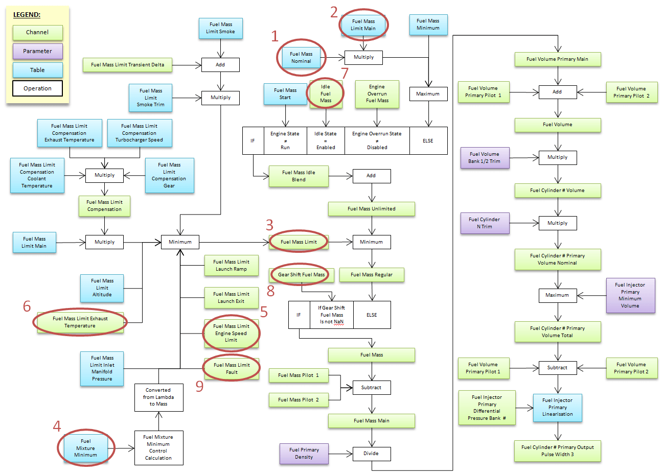
Notice: This section refers to the main injection pulse flowchart on the following page (Fig. 1).

  • This package delivers fuel in proportion to the accelerator pedal position (see 1 & 2 in Fig 1, page 1). The fuel mass can then be limited (see 3 in Fig 1) by a series of tables and calculations, including:
    • Fuel Mass Limit Smoke
    • Fuel Mass Limit Smoke Trim
    • Fuel Mass Limit Compensation Coolant Temperature
    • Fuel Mass Limit Compensation Exhaust Temperature
    • Mass Fuel Limit Compensation Turbocharger Speed
    • Fuel Mass Limit Compensation Gear
    • Fuel Mass Limit Altitude
    • Exhaust temperature fuel mass limit
    • Fuel mass limit failure
    • Fuel Mass Limit Intake Manifold Pressure
    • Minimum fuel mixture
  • The Minimum Fuel Mixture Control system applies an adjustment to the Fuel Mass Limit to ensure that the Exhaust Lambda is not richer than the user defined limit, which is set in the Minimum Fuel Mixture table (see 4 in Fig 1).
  • The engine speed limitation control system varies the fuel mass to maintain engine speed within user-defined limits (see 5 in Fig. 1).
  • Exhaust temperature protection The control system that limits the fuel mass (see 6 in Fig. 1) based on the exhaust temperature can be used to prevent overheating of the exhaust components (i.e. turbocharger).
  • Idle speed control with closed loop fuel mass control (see 7 in Fig 1) to ensure smooth and stable engine idle speed. Ramp Down functionality can also be used to provide a smooth transition to idle mode.
  • Power-assisted gear changes with independent fuel mass control (see 8 in Fig. 1). Up and down gear changes can be adjusted independently via separate tables.
  • Configurable control of up to 2 proportional and 1 synchronous direct injection fuel pumps.
  • Fuel mass limits (see 9 in Fig. 1) can be set for each of the 61 individual warnings that can be monitored with the warning system. The warning system determines whether a measurement is outside normal operating conditions or whether a sensor, input or output is defective.

    Notices are included for:

    • Engine oil pressure
    • Engine crankcase pressure
    • Direct Fuel Primary Pressure Bank 1 & 2
    • Primary fuel pressure
    • Coolant temperature
    • Inlet air temperature
    • Engine oil temperature
    • Exhaust lambda
    • Exhaust temperature
    • Exhaust pressure
    • Engine speed
Fig 1: Main injection pulse flowchart
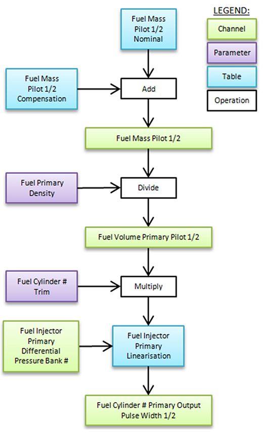
Pilot pulse system

Support for up to two pilot pulses before the main pulse to allow for smoother operation and reduced noise. The fuel mass of each pilot pulse can vary with engine speed and the total mass of fuel being delivered. Pilot fuel mass can also be compensated for coolant temperature. Pilot pulse timing can be relative to TDC, the main pulse, or calculated. Timing can also be varied with engine speed and total fuel mass and can be compensated for coolant and engine load temperature.

Fig 2: Pilot injection pulse flowchart
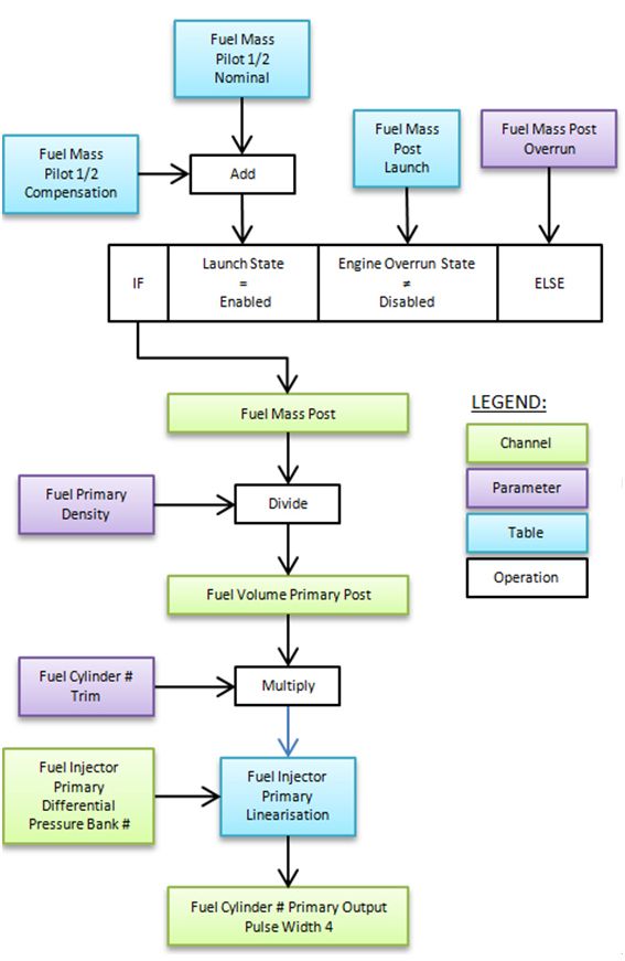
Post-pulse system

A single postpulse after the main pulse can be added to reduce emissions or increase thrust without affecting engine power. The postpulse fuel mass can vary with engine speed and the total mass of fuel being delivered. The pilot fuel mass can also be compensated for by coolant temperature.

Postpulse timing can be relative to TDC, the main pulse or calculated. Timing can also be varied with engine speed and total fuel mass and can be compensated for coolant temperature. Postpulse can be independently controlled at engine coast and launch with options to disable/enable postpulse during gear changes and traction control.

Fig 3: Post-injection pulse flow diagram

Known OE engines that are suitable:

Engine familyEngine designationYearVehicle platformECUComment
Toyota KD1KD-FTV2012-2015Hilux KUN16R, KUN26RM130 or M150*, M141 or M142Medium voltage inductive injectors
Toyota GD1GD-FTV2015-2018Hilux GUN126RM141 or M142Medium voltage inductive injectors
Toyota RV1VD-FTV2007-2017Landcruiser 200M130 or M150*, M141High voltage inductive injectors
Duratorq 3.2ZSD Puma (P5AT)2011-2018Ford Ranger T6M141Piezo injectors
Duratorq 3.2MZ-CD 3.22011-2018Mazda BT50M141Piezo injectors
Mitsubishi 4N14N152015-2018Mitsubishi Triton L200MQM141High voltage inductive injectors
Isuzu J4JJ1-TCX2012-2018Isuzu D-MaxM141 or M142Medium voltage inductive injectors
GM DuramaxLWN2012-2018Holden ColoradoM142Medium voltage high current inductive injectors
VM MotorsR-4028DOHC2010-2018Jeep WranglerM142Medium voltage high current inductive injectors

*The M130 and M150 ECUs can only be used in conjunction with the OE injector drive box.

Engine Rotation Modes

Starting with M1 System 1.4.00.0056

This list only refers to engine modes that are relevant to known diesel engines.

  • Bosch 140 40 – General Motors LLT, Audi BXA/Lamborghini LP560, Mazda L3-VDT
  • Camshaft one missing four stroke
  • Camshaft two missing four strokes
  • Crankshaft One Missing Four Strokes
  • Crankshaft One Missing Two Strokes
  • Crankshaft Two Missing Four Strokes
  • Crankshaft Two Missing Two Strokes
  • General Motors DMAX LMM – General Motors 6.6L Duramax LMM diesel engines (late 2007 – early 2011) when the eighth digit of the VIN number is 6.
  • Isuzu 4JK1
  • Mitsubishi Fuso 4P10 (also Agco Sisu Power 49G)
  • Mitsubishi Fuso 6M60 – 2015 Fuso TKG-FK61F
  • Multi Tooth Four Stroke
  • Multi Tooth Two Stroke
  • Nissan YS23DDT – Diesel Navara
  • Scania DC16
  • Scania SGL12A
  • Toyota 1GD FTV – 2.8L common rail diesel (2015 – )
  • Toyota 1KD FTV – 3.0L common rail diesel (2000 – )
  • Volvo D11C – D11C truck engine (FM450 Platform)

Pinout Example

M142 A connector – 34 ways
Mating connector: Tyco Superseal 34 Position Keying 2 – MoTeC # 65067
PinDesignationFull nameOE pinFunction
A01AT5Analog Temperature Input 5 Exhaust temperature sensor
A02AT6Analog temperature input 6 Coolant temperature sensor
Answer A03AV15Analog voltage input 15  
A04AV16Analog voltage input 16  
A05AV17Analog voltage input 17  
A06INJ_D1A_NEGDirect Injector 1A – Fuel Cylinder 1 Primary Outlet –
A07INJ_D1A_POSDirect Injector 1A + Fuel Cylinder 1 Primary Outlet +
A08INJ_D1B_POSDirect Injector 1B+ Fuel Cylinder 4 Primary Outlet +
A09INJ_D1B_NEGDirect Injector 1B – Fuel Cylinder 4 Primary Outlet –
Answer 10SEN_5V0_C15.0VC Sensor  
Answer 11LA_NB1Lambda narrow input 1  
Answer 12LA_NB2Lambda 2 Narrow Entry  
Answer 13BEAT 3Detonation input 3  
Answer 14BEAT 4Detonation input 4  
Answer 15DIG2Digital input 2  
Answer 16DIG3Digital input 3  
Answer 17DIG4Digital input 4  
Answer 18SEN_5V0_C25.0VC Sensor  
A19SEN_5V0_B25.0VB Sensor 5V analog signal sensor
Answer 20LINLIN Bus  
A21RS232_RXRS232 Receive  
ANSWER 22RS232_TXRS232 transmission  
A23DIG1Digital input 1  
A24BAT_NEG3Negative Battery Floor
A25BAT_NEG4Negative Battery Floor
A26SEN_0V_C1Sensor 0V C  
A27SEN_0V_C2Sensor 0V C  
A28CAN3_HICAN Bus 3 High  
A29CAN3_LOCAN Bus 3 Low  
Answer 30CAN2_HICAN Bus 2 High  
A31CAN2_LOCAN Bus 2 Low  
A32BAT_NEG5Negative Battery Floor
A33SEN_0V_B1Sensor 0V B  
Answer 34SEN_0V_A1Sensor 0V A  
M142 Connector B – 26-way
Mating connector: Tyco Superseal 26 Position Keying 3 – MoTeC # 65068
PinDesignationFull nameOE pinFunction
B01OUT_HB9Half bridge exit 9 EGR actuator servo motor –
B02OUT_HB10Half bridge exit 10 EGR actuator servo motor +
B03UDIG8Universal digital input 8  
B04UDIG9Universal Digital Input 9  
B05UDIG10Universal Digital Input 10 Engine running switch
B06UDIG11Universal Digital Input 11 Air box mass flow sensor
B07UDIG12Universal digital input 12 Boost servo actuator position sensor
B08INJ_LS5Low Side Injector 5  
B09INJ_LS3Low Side Injector 3  
B10AV9Analog voltage input 9 Direct Primary Fuel Pressure Bank 1
B11AV10Analog voltage input 10  
B12AV11Analog voltage input 11 Engine oil pressure sensor
B13BAT_POS2Positive Battery ECU battery voltage
B14INJ_LS6Low Side Injector 6  
B15INJ_LS4Low Side Injector 4 ECU Power Relay
B16AV12Analog voltage input 12  
B17AV13Analog voltage input 13  
B18AV14Analog voltage input 14  
B19BAT_POS3Positive Battery ECU battery voltage
B20OUT_HB7Half bridge exit 7 Throttle Servo Bank Motor 1 –
B21OUT_HB8Half bridge exit 8 Throttle Servo Bank 1 Motor +
B22INJ_D2A_NEGDirect Injector 2A – Fuel Cylinder 2 Primary Outlet –
B23INJ_D2A_POSDirect Injector 2A + Fuel Cylinder 2 Primary Outlet +
B24INJ_D2B_POSDirect Injector 2B+  
B25INJ_D2B_NEGDirect Injector 2B –  
B26SEN_5V0_A25.0VA Sensor  
M142 Connector C – 34 ways
Mating Connector C: Tyco Superseal 34 Position Keying 1 – MoTeC # 65044
PinDesignationFull nameOE pinFunction
C01OUT_HB2Half bridge exit 2 Primary Fuel Pressure Direct Bank Pump 1 +
C02SEN_5V0_A15.0VA Sensor  
C03IGN_LS1Low side ignition 1  
C04IGN_LS2Low Side Ignition 2  
C05IGN_LS3Low side ignition 3  
C06IGN_LS4Low side ignition 4  
C07IGN_LS5Low side ignition 5 Ignition cylinder 1 (timing light output)
C08IGN_LS6Low side ignition 6  
C09SEN_5V0_B15.0VB Sensor 5V analog signal sensor
C10BAT_NEG1Negative Battery Floor
C11BAT_NEG2Negative Battery Floor
C12IGN_LS7Low Side Ignition 7  
C13IGN_LS8Low side ignition 8  
C14AV1Analog voltage input 1 Main accelerator pedal sensor
C15AV2Analog voltage input 2 Accelerator pedal sensor tracking
C16AV3Analog voltage input 3  
C17AV4Analog voltage input 4  
C18OUT_HB1Half bridge exit 1 Primary Fuel Pressure Direct Bank Pump 1 –
C19INJ_D3A_POSDirect Injector 3A + Fuel Cylinder 3 Primary Outlet +
C20INJ_D3B_POSDirect Injector 3B+  
C21INJ_D4A_POSDirect Injector 4A +  
C22INJ_D4B_POSDirect Injector 4B+  
C23INJ_LS1Low Side Injector 1  
C24INJ_LS2Low Side Injector 2  
C25AV5Analog voltage input 5  
C26BAT_POS1Positive Battery ECU battery voltage
C27INJ_D3A_NEGDirect Injector 3A – Fuel Cylinder 3 Primary Outlet –
C28INJ_D3B_NEGDirect Injector 3B –  
C29INJ_D4A_NEGDirect Injector 4A –  
C30INJ_D4B_NEGDirect Injector 4B –  
C31OUT_HB3Half bridge exit 3 Primary Fuel Pump
C32OUT_HB4Half bridge exit 4  
C33OUT_HB5Half bridge exit 5 Boost Servo Actuator Motor –
C34OUT_HB6Half bridge exit 6 Boost + Servo Actuator Motor
M142 Connector D – 26 Ways
Coupling Connector D: Tyco Superseal 26 Position Keying 1 – MoTeC #65045
PinDesignationFull nameOE pinFunction
D01UDIG1Universal digital input 1 Engine speed sensor
D02UDIG2Universal digital input 2 Intake camshaft position sensor
D03AT1Analog temperature input 1  
D04AT2Analog temperature input 2 Intake air temperature sensor
D05AT3Analog Temperature Input 3 Primary fuel temperature sensor
D06AT4Analog temperature input 4  
D07BEAT 1Detonation input 1  
D08UDIG3Universal Digital Input 3  
D09UDIG4Universal digital input 4  
D10UDIG5Universal Digital Input 5  
D11UDIG6Universal Digital Input 6 Throttle servo bank 1 position sensor
D12BAT_BAKBattery Backup  
D13BEAT 2Detonation input 2  
D14UDIG7Universal digital input 7  
D15SEN_0V_A2Sensor 0V A 0V sensor for digital signals
D16SEN_0V_B2Sensor 0V B 0V sensor for digital signals
D17CAN1_HICAN Bus 1 High MoTeC 1 Mbit/sec CAN
D18CAN1_LOCAN Bus 1 Low MoTeC 1 Mbit/sec CAN
D19SEN_6V36.3V Sensor  
D20AV6Analog voltage input 6 EGR actuator servo position sensor
D21AV7Analog voltage input 7  
D22AV8Analog voltage input 8 Intake manifold pressure sensor
D23ETH_TX+Ethernet Transmission +Green/White Ethernet 
D24ETH_TX-Ethernet Transmission –Green Ethernet 
D25ETH_RX+Ethernet + ReceptionOrange/White Ethernet 
D26ETH_RX-Ethernet Reception –Orange Ethernet 

Downloads